view on the diagram
M O D I F I C A T I O N S : ENGINE - FGA Motorsport Chip
FGA Motorsport Powerbox installation on a VVC
1) Open the front bonnet and disconnect the Negative from the battery.
2) Locate the engine control unit (ECU): open boot, remove inspection grill
and you will find it at your lefthand side, mounted to the wall of the boot.
3) Disconnect the plugs. It's also advisable to deattach the loom a bit further
too... giving the opportunity to access the wiring loom more easily.
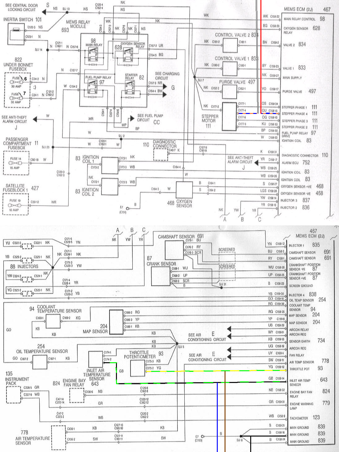
4) Find wire at pin number B15 and cut it (red
connector, orange/blue cable responsible for the
stepper motor signal)
5) Connect the red wire of the Powerbox to the
orange/blue cable that runs to the ECU
6) Connect the white wire of the Powerbox to the
other end of the orange/blue cable.
7) Find wire at pin number B16 (red connector,
black cable) and connect the black
wire of the Powerbox with it.
8) Find wire at pin number A12 (black connector,
green/yellow cable responsible for the signal comming
from the throttle position sensor) and connect the brown
wite of the Powerbox with it.
9) Find wire at pin number A14 (black connector,
green/black cable responsible for the signal of
the air inlet teperature sensor) and connect the blue
wire of the Powerbox with it.
10) Make sure all connections are insulated and strongly connected. Reconnect
the plugs with the ECU back again.
11) Reconnect the negative of the battery
12) Start-up the engine and go out for a spin.
Please note: there are differences between versions of MEMS and the above fitting instructions need to be verified before going through this procedure on another car. However above instructions made fitting on Bruno's VVC possible and well worth this mod.
view on the diagram
back to:
Modifications - Tuning - Engine - Chips
Modifications - Tuning - Engine - Chips
- FGA Motorsport
Thanks to: Paul actually doing the installation; Bruno providing a VVC, Dieter making the diagram available, FGA motorsport providing the magical box.